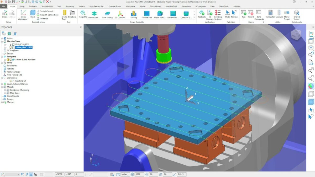
PowerMill Ultimate empowers you to generate efficient and precise 3-axis toolpaths, forming the foundation for a vast array of machining operations. While 5-axis machining offers additional freedom, 3-axis toolpaths remain a cornerstone of CNC machining, offering a balance of simplicity, efficiency, and effectiveness for a wide range of parts and geometries. This comprehensive guide delves into the world of 3-axis toolpath creation in PowerMill Ultimate, equipping you with the knowledge and techniques to craft exceptional toolpaths for your machining endeavors.
Understanding the Core Principles: The Power of Three
3-axis machining restricts tool movement along the X, Y, and Z axes. This seemingly limited approach offers a surprising degree of versatility for various machining tasks. Here’s a breakdown of the core principles that govern 3-axis toolpath generation:
Tool Geometry: The shape and size of the cutting tool significantly influence the capabilities and limitations of the 3-axis approach. Common 3-axis tool geometries include end mills, ball nose end mills, drills, and taps, each suited for specific machining tasks. Selecting the appropriate tool for the desired feature and material is paramount for efficient chip removal and achieving the required surface finish.
Workpiece Geometry: The complexity of the workpiece geometry dictates the suitability of 3-axis machining. Simple features like pockets, slots, and flat surfaces are ideally suited for 3-axis toolpaths. Conversely, intricate shapes with deep undercuts or internal cavities might require the additional freedom offered by 5-axis machining (covered in a future installment).
Toolpath Strategies: PowerMill offers a comprehensive library of toolpath strategies specifically designed for 3-axis machining. These strategies define how the tool moves along the X, Y, and Z axes to achieve the desired machining results. Common strategies include:
- Linear Milling: The tool follows a straight line path along the X or Y axis, ideal for machining pockets, slots, and grooves.
- Ramp Milling: The tool gradually enters and exits the material at an angle, minimizing chip load and tool deflection, often used for roughing operations.
- Pocket Milling: The tool traverses a defined pocket or cavity using various techniques like raster milling (back-and-forth passes) or spiral milling for improved chip evacuation.
- Hole Making: This strategy defines toolpaths for drilling, reaming, tapping, and other hole-making operations using the appropriate drilling and threading tools.
By understanding these core principles, you establish a solid foundation for creating effective 3-axis toolpaths in PowerMill Ultimate.
Building Your Toolpath Arsenal: A Step-by-Step Guide
Creating a 3-axis toolpath in PowerMill Ultimate involves a series of well-defined steps:
Define the Stock Model: An accurate representation of the raw material (stock) is crucial. PowerMill allows you to create a stock model from the CAD model of the finished part by virtually removing the machined features. Alternatively, you can import the stock model from a scan of the actual material.
Select the Toolpath Strategy: Based on the feature you want to machine and the desired outcome, choose the appropriate toolpath strategy from PowerMill’s library. Each strategy offers various options and parameters for customization.
Geometry Selection: Define the geometry that the toolpath will follow. This might involve selecting a closed profile for a pocket, a line for a slot, or a series of points for drilling operations.
Tool Selection: Choose the cutting tool best suited for the specific machining task and material. PowerMill’s extensive tool library offers a variety of options, and you can define specific tool properties like diameter, cutting length, and number of flutes.
Parameter Definition: Each toolpath strategy comes with a set of parameters that govern the cutting process. These parameters include:
- Cutting Conditions: Spindle speed (RPM), feed rate (mm/min or in/min), and chip load (mm/tooth or in/tooth) significantly influence material removal rate, surface finish, and tool life. PowerMill offers recommendations based on the selected tool and material, but user experience and material testing can further refine these recommendations.
- Step-Over: The distance between adjacent tool passes during toolpath generation. A smaller step-over results in a smoother surface finish but requires more machining time.
- Approach and Retract Strategies: Define how the tool enters and exits the material, impacting factors like surface finish and tool wear.
Toolpath Preview and Verification: PowerMill allows you to preview the generated toolpath to visualize its movement and identify any potential issues.
