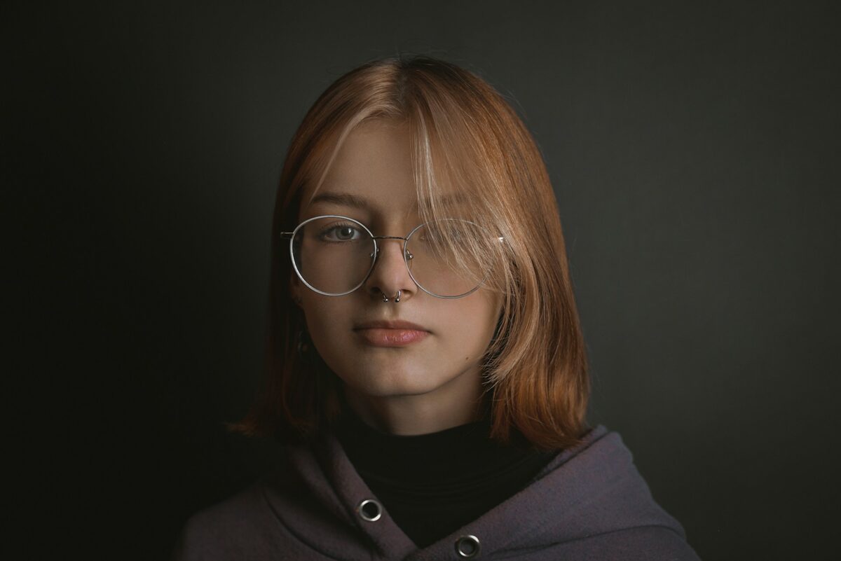
Professional portraits: The most effective retouching techniques
When it comes to portrait retouching, the goal is to enhance natural attractiveness while at the same time keeping authenticity. When you over-edit your photos, the skin in the pictures might end up appearing like plastic. On the other hand, if you don’t edit them enough, there can be distractions in the background that take attention away from the topic. In order to achieve professional retouching, one must find a meticulous balance between correcting imperfections, highlighting strengths, and ensuring that the finished picture remains credible. This post provides an overview of the most effective retouching methods that pros use in Photoshop to consistently and quickly clean pictures.
1. Begin by Using a Workflow that Does Not Cause Damage
When retouching, always be sure to do it in a manner that permits reversibility.
Make sure to make a copy of the background layer before you start making any changes.
Direct alterations should be avoided in favor of Adjustment Layers.
Make use of layer masks in order to localize adjustments.
For the purpose of having filters that are adaptable, convert items into Smart Objects.
This guarantees that you will be able to make adjustments to or undo alterations without having to start all over again.
2. Utilize Healing Tools to Clean Up
When it comes to dealing with minor imperfections, dust, and stray hairs, the most effective approach is to use the appropriate equipment:
The Spot Healing Brush Tool: Fast solutions for little imperfections.
Healing Brush Tool: Sample select regions for more controlled outcomes.
The Clone Stamp Tool is a valuable instrument for the purpose of eliminating distractions while yet maintaining texture.
Patch Tool: The ideal tool for repairing bigger uneven regions, such as creases in clothes or skin patches.
For a natural blend, maintain a modest level of opacity (between 70 and 90 percent).
3. Make Skin Tones More Uniform
Compared to texture, an uneven skin tone is often more of a distraction. Utilization
Dodge and Burn: Make dark regions slightly brighter and highlights slightly darker in order to achieve a balance in tones.
Selective Color Adjustment Layers: These layers may be used to reduce the amount of redness or yellowing in the skin.
Frequency Separation (for advanced users): Separate texture from color and modify tones without sacrificing skin detail.
Edits should always be modest, and the skin should continue to seem realistic.
4. Advanced Skin Retouching Using Frequency Separation
When it comes to intricate skin work, this is the preferred tool for professionals:
Make two copies of the topic layer.
For the sake of distinguishing between colors and tones, name one “Low Frequency,” and for the purpose of distinguishing between textures, name the other “High Frequency.”
Make the Low Frequency layer blurry by using a Gaussian Blur with a radius of five to ten pixels, depending on the resolution.
In order to isolate the texture, go to the High Frequency layer and use the “Apply Image” option.
You now have the ability to smooth out uneven tones on Low Frequency and eliminate defects on High Frequency independently of one another.
This guarantees that pores will not be damaged while also making the skin tone more consistent.
5. Using Dodge and Burn to Create Dimension
The pictures seem to be polished and three-dimensional because of the subtle modifications made to light and shadow.
Make two Curves Adjustment Layers, one of which is brighter and one of which is darker.
Make sure that the masks are filled with black paint.
Use a delicate white brush at a low opacity (5–10%) to paint regions in order to gradually lighten or darken them as desired.
You can use dodge and burn to:
- Emphasize the cheekbones, jawlines, and eyes of the model.
- Make the shadows underneath the eyes less noticeable.
- Reduce highlights on skin that is greasy.
6. Ways to Make Your Eyes More Appealing
Because the eyes are the main focus of the majority of pictures, they need particular attention:
Make the whites just a little brighter, but avoid using pure white.
- Make use of the Dodge tool to lighten the iris and the Burn tool to darken the rim of the iris in order to increase the contrast.
- You may sharpen the iris by using either the Unsharp Mask or the High Pass Filter on a selective basis.
- Use a Healing Brush with a low opacity setting to reduce the appearance of red veins.
- In order to prevent the “glowing eyes” look, it is important to keep improvements to a minimum.
7. Whitening of Teeth
Distraction may be caused by teeth that are yellowish in color:
- Make a Hue/Saturation Adjustment Layer.
- Yellows should be selected, and saturation should be decreased.
- Make the brightness a little more intense.
- Conceal the adjustment in such a way that it only affects the teeth.
- This procedure prevents the results from seeming artificial or too white.
8. Lip Augmentation
Subtle adjustments give the lips a larger and healthier appearance:
For shine, use the Dodge Tool at low exposure (5–10%) on highlights.
Use a burn tool to give the edges more depth.
In the event that the lips seem as if they have lost their color, you may restore their brightness by making a little change to the hue and saturation.
9. Hair Retouching
Portraits might come out as unkempt when there are stray hairs and frizz:
- On plain backdrops, use the Spot Healing Brush to eliminate flyaways.
- When dealing with backgrounds that are more complicated, the Clone Stamp tool, together with a delicate brush, should be used.
- Employing a dodging technique in the places that are most likely to attract light can give the hair a glossy appearance.
- When it comes to volume and realism, you should refrain from over-smoothing the corners of your hair.
10. Plugins for Smoothing Skin (Optional)
Although hand retouching is the most effective method for maintaining control, plug-ins such as Portraiture, Retouch4Me, and Luminar help expedite the procedure. Because they have the potential to over-smooth and produce outcomes that are not realistic, they should be used carefully. It is essential to always pair them with hand touch-ups.
11. Giving Your Appearance a Finished Look by Sharpening
After the retouching is complete, selectively sharpen the image:
- Make a copy of the combined layer and apply a High Pass Filter on it.
- Set the blending mode to either Overlay or Soft Light.
- Exclude every part of the image except the eyes, mouth, and details of the hair.
- Do not sharpen the skin since it will make blemishes and defects more noticeable.
12. Color Grading and the Last Details
The portrait is brought together by the color grading:
- For a constant mood, use Curves or Color Lookup Tables (LUTs).
- Warm tones often complement the complexion, whilst cooler tones contribute to a more dramatic appearance.
- To direct attention to the topic, use a discreet vignette.
13. Exporting for Web Versus Print
For the web, export in JPEG format with minor sharpening for screen, using the sRGB color profile.
When printing, it is best to use Adobe RGB or CMYK, TIFF/PSD format, and avoid excessive sharpening.
14. Typical Errors That Should Be Avoided
Exaggerated efforts to make the skin smooth, resulting in a plastic-like appearance
- Excessive whitening of one’s teeth or eyes, which results in an artificial radiance.
- Disregarding the inherent asymmetry of faces (faces should not have the appearance of being clones of one another).
- When texture is not taken into account, the skin seems unnatural since there are no pores.
- When it comes to retouching, precision is essential, hence it is recommended that you use global changes rather than local alterations.
When it comes to professional image retouching, presenting someone in the most flattering way possible is more important than modifying their look. The objective is to eliminate distractions, accentuate natural qualities, and ensure that the end outcome is realistic. It is guaranteed that customers will be more than satisfied with the polished results that are achieved via mastering methods like as healing, frequency separation, dodge and burn, and selective sharpening. The sign of a competent retoucher is that they know when they have done enough, and with experience, you will also develop this skill.