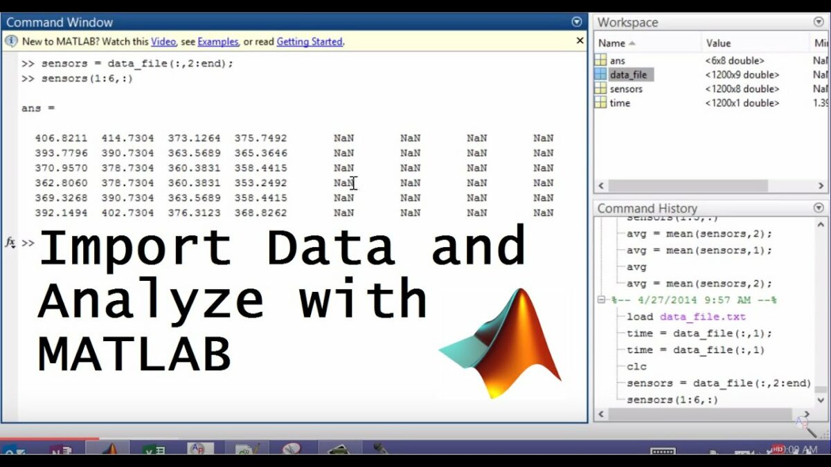
Introduction: Importing data into MATLAB from different file formats is a fundamental task for data analysis, visualization, and modeling. MATLAB provides robust tools and functions to import data from a variety of file formats, including CSV, Excel, text, and more. This comprehensive guide aims to provide a detailed overview of how to import data into MATLAB from different file formats, offering step-by-step insights and expert tips to empower users to efficiently handle data from diverse sources for their projects and tasks.
Understanding Data Importation in MATLAB: In MATLAB, data importation refers to the process of reading external data files and loading their contents into MATLAB variables or data structures for further analysis and processing. MATLAB supports various file formats for data importation, each with its own syntax, functions, and considerations. Understanding how to import data from different file formats is essential for working with real-world data sets and integrating external data sources into MATLAB workflows seamlessly.
Key Concepts of Data Importation in MATLAB: Before delving into importing data from different file formats, it’s essential to understand some key concepts and considerations:
- File Formats: MATLAB supports a wide range of file formats for data importation, including CSV (Comma-Separated Values), Excel spreadsheets, text files, HDF5, MAT files, and more.
- Import Functions: MATLAB provides built-in functions and tools for importing data from different file formats, such as “readtable” for reading tabular data, “csvread” for reading CSV files, “xlsread” for reading Excel files, and “fread” for reading binary files.
- Data Preprocessing: Preprocessing steps, such as data cleaning, formatting, and transformation, may be required after importing data into MATLAB to prepare it for analysis and visualization.
- Error Handling: Handling errors and exceptions during data importation is crucial for ensuring data integrity, reliability, and robustness in MATLAB workflows.
Importing Data from Different File Formats: The process of importing data into MATLAB from different file formats involves several steps, depending on the specific file format and data structure. Here’s a comprehensive guide to importing data from common file formats:
- Importing CSV Files:
- Use the “readtable” function to import data from a CSV file into a table variable. For example:
matlabdata = readtable('data.csv');
- Importing Excel Files:
- Use the “xlsread” function to import data from an Excel file into MATLAB arrays or matrices. For example:
matlab[data, headers] = xlsread('data.xlsx');
- Importing Text Files:
- Use functions like “fscanf” or “textscan” to import data from text files with custom formats or delimiters. For example:
matlabfileID = fopen('data.txt', 'r');
data = fscanf(fileID, '%f');
fclose(fileID);
- Importing HDF5 Files:
- Use the “h5read” function to import data from HDF5 files into MATLAB variables or data structures. For example:
matlabdata = h5read('data.h5', '/dataset');
- Importing MAT Files:
- Use the “load” function to import data from MAT files (MATLAB data files) into MATLAB workspace variables. For example:
matlabload('data.mat');
Best Practices for Data Importation in MATLAB: In addition to following the step-by-step guidelines outlined above, here are some best practices to optimize data importation in MATLAB:
- Validate Input Files: Check the integrity, format, and structure of input files before importing data to ensure compatibility and avoid potential errors or issues.
- Handle Missing Data: Handle missing or incomplete data appropriately during importation, using techniques such as data imputation, interpolation, or exclusion.
- Convert Data Types: Convert imported data to appropriate MATLAB data types (e.g., numeric, string, datetime) based on the nature of the data and the intended analysis or visualization tasks.
- Use Import Options: Explore and leverage import options and parameters available in MATLAB functions (e.g., delimiter, header lines, column names) to customize the import process and handle specific file formats or configurations.
- Automate Importation: Automate repetitive importation tasks using scripts, functions, or batch processing techniques to streamline workflows and improve efficiency.
Conclusion: Importing data into MATLAB from different file formats is a fundamental aspect of data analysis, visualization, and modeling workflows. By following the comprehensive guide and best practices outlined above, users can efficiently handle data from diverse sources, integrate external data sources into MATLAB workflows seamlessly, and unlock the full potential of MATLAB for their projects and tasks. With its powerful import functions, versatile data structures, and extensive documentation, MATLAB empowers users to explore, analyze, and visualize data with ease, enabling data-driven insights and discoveries across various domains and disciplines. Whether it’s processing sensor data, analyzing experimental results, or integrating external databases, MATLAB provides a flexible and robust platform for importing, manipulating, and exploring data to extract meaningful insights and drive impactful decision-making and innovation.


