Excel is a versatile tool for managing and analyzing data, and the HLOOKUP function is an essential feature for retrieving information based on horizontal lookup. Whether you’re organizing financial data, managing inventory, or creating complex spreadsheets, understanding how to use the HLOOKUP function can greatly enhance your ability to extract relevant information efficiently. In this comprehensive guide, we’ll delve into everything you need to know about using the HLOOKUP function in Excel, from basic syntax to advanced techniques and real-world applications.
Table of Contents
- Introduction
- Benefits of Using the HLOOKUP Function
- Basic Syntax and Usage
- Practical Examples
- Horizontal Lookup with HLOOKUP
- Handling Approximate Matches
- Using HLOOKUP with Multiple Criteria
- Advanced Techniques
- Nesting HLOOKUP with Other Functions
- Dynamic Range Selection
- Incorporating Error Handling
- Handling Errors
- Common Errors and Troubleshooting
- Ensuring Data Integrity
- Tips and Tricks
- Optimizing Performance
- Using Named Ranges
- Conditional Formatting with HLOOKUP
- Real-World Applications
- Financial Analysis
- Inventory Management
- Project Planning
- Best Practices
- Structuring Data for HLOOKUP
- Documenting Formulas
- Testing and Validating Results
- Conclusion
1. Introduction
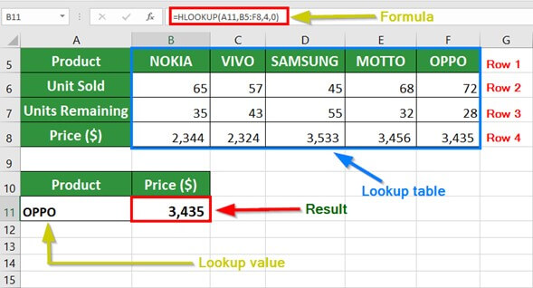
The HLOOKUP function in Excel is designed to perform a horizontal lookup by searching for a specified value in the first row of a table or range and returning a value from a corresponding row. This makes it a valuable tool for retrieving data based on predefined criteria, especially when dealing with large datasets or complex spreadsheets.
2. Benefits of Using the HLOOKUP Function
- Efficiency: Quickly retrieve specific data points from large tables or ranges without manually searching through rows.
- Accuracy: Ensure accurate results by specifying search criteria and allowing Excel to handle the lookup process.
- Versatility: Use HLOOKUP to perform a wide range of tasks, from basic data retrieval to more complex analysis.
- Time-Saving: Streamline data analysis workflows by automating the lookup process with the HLOOKUP function.
3. Basic Syntax and Usage
The basic syntax of the HLOOKUP function is as follows:
=HLOOKUP(lookup_value, table_array, row_index_num, [range_lookup])
- lookup_value: The value to search for in the first row of the table.
- table_array: The range of cells that contains the data.
- row_index_num: The row number in the table from which to retrieve the value.
- range_lookup: Optional. A logical value that specifies whether to perform an approximate match (TRUE) or an exact match (FALSE).
4. Practical Examples
Horizontal Lookup with HLOOKUP
To perform a basic horizontal lookup with the HLOOKUP function:
=HLOOKUP("Product C", A1:E5, 3, FALSE)
This formula searches for “Product C” in the first row of the range A1:E5 and returns the value from the third row.
Handling Approximate Matches
To perform an approximate match with HLOOKUP:
=HLOOKUP(750, A1:E5, 2, TRUE)
This formula searches for the closest match to 750 in the first row of the range A1:E5 and returns the value from the second row.
Using HLOOKUP with Multiple Criteria
To use HLOOKUP with multiple criteria, combine it with other functions like INDEX and MATCH:
=INDEX(A1:E5, MATCH("Product C", A1:A5, 0), MATCH("Quarter 3", A1:E1, 0))
This formula first uses MATCH to find the row and column numbers corresponding to “Product C” and “Quarter 3,” respectively, and then uses INDEX to return the value at the intersection of the identified row and column.
5. Advanced Techniques
Nesting HLOOKUP with Other Functions
Nest HLOOKUP within other functions to create more complex lookup formulas:
=IFERROR(HLOOKUP("Product D", A1:E5, 3, FALSE), "Not Found")
This formula uses IFERROR to handle errors gracefully by displaying a custom message (“Not Found”) if the lookup value is not found in the table.
Dynamic Range Selection
Use dynamic range selection to make HLOOKUP formulas more flexible:
=HLOOKUP("Product A", OFFSET(A1, 0, 0, COUNTA(A:A), 5), 3, FALSE)
This formula uses OFFSET to dynamically adjust the range based on the number of non-empty cells in column A, allowing for easier data expansion.
Incorporating Error Handling
Incorporate error handling techniques to improve the robustness of HLOOKUP formulas:
=IF(ISERROR(HLOOKUP("Product E", A1:E5, 3, FALSE)), "Not Found", HLOOKUP("Product E", A1:E5, 3, FALSE))
This formula uses ISERROR to check for errors and display a custom message (“Not Found”) if the lookup value is not found in the table.
6. Handling Errors
Common Errors and Troubleshooting
- #N/A Error: This error occurs if the lookup value is not found in the first row of the table.
- #REF! Error: This error occurs if the specified range is invalid or the row_index_num is outside the range of the table.
Ensuring Data Integrity
Regularly review and validate HLOOKUP formulas to ensure that they are returning accurate results, especially when dealing with large datasets or complex lookup criteria.
7. Tips and Tricks
Optimizing Performance
To improve the performance of HLOOKUP formulas, consider reducing the size of the table or using named ranges to simplify the formula syntax.
Using Named Ranges
Define named ranges for the table_array parameter to make HLOOKUP formulas more readable and easier to maintain.
Conditional Formatting with HLOOKUP
Use HLOOKUP formulas in conjunction with conditional formatting to highlight specific data points or trends in your Excel worksheets.
8. Real-World Applications
Financial Analysis
Use HLOOKUP to retrieve financial data such as sales figures, expenses, or profit margins for analysis and reporting purposes.
Inventory Management
Use HLOOKUP to track inventory levels, monitor stock movements, and generate inventory reports based on predefined criteria.
Project Planning
Use HLOOKUP to retrieve project-related data such as timelines, milestones, or resource allocations for project planning and management.
9. Best Practices
Structuring Data for HLOOKUP
Organize data in a tabular format with clear headers to facilitate the use of HLOOKUP formulas.
Documenting Formulas
Document HLOOKUP formulas by adding comments or annotations to explain their purpose and usage.
Testing and Validating Results
Regularly test and validate HLOOKUP formulas against known data points to ensure accuracy and reliability.