Cable markers play a crucial role in electrical design, providing clear identification and organization of cables within schematic diagrams and wiring documentation. In Autodesk Electrical, the cable marker feature offers powerful tools to create, customize, and manage cable markers, ensuring accuracy, consistency, and efficiency in wiring design processes. In this comprehensive guide, we will explore the intricacies of creating and using cable markers in Autodesk Electrical, providing detailed instructions, best practices, and expert tips to help you master this essential aspect of electrical design.
Understanding the Significance of Cable Markers
Cable markers serve several key purposes in electrical design:
- Identification: Cable markers provide clear identification of cables, wires, and conductors within schematic diagrams, facilitating installation, troubleshooting, and maintenance activities.
- Organization: By assigning unique identifiers to cables, cable markers help organize and manage wiring systems, minimizing errors and confusion during assembly and operation.
- Documentation: Cable markers ensure consistency and accuracy in wiring documentation, enhancing readability and comprehension of schematic diagrams and wiring diagrams.
Creating Cable Markers in Autodesk Electrical
Now, let’s delve into the step-by-step process of creating cable markers within Autodesk Electrical:
Step 1: Accessing the Cable Marker Tools
- Menu Navigation: Navigate to the “Cable Markers” menu or toolbar within Autodesk Electrical to access the cable marker tools.
- Workspace Configuration: Set up the workspace to display the cable marker interface, which typically includes options for marker creation, customization, and placement.
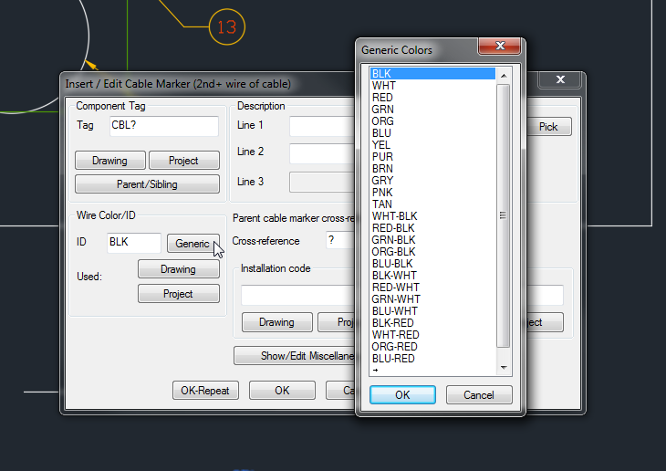
Step 2: Defining Cable Marker Properties
- Marker Properties: Define the properties of the cable marker, including marker type, format, size, and content.
- Marker Styles: Customize marker styles, such as font type, size, color, and alignment, to match project requirements and design preferences.
Step 3: Placing Cable Markers
- Marker Placement: Place cable markers at appropriate locations along cables within the schematic diagram, ensuring visibility and readability.
- Automatic Placement: Utilize automatic placement tools to place cable markers based on predefined settings and criteria, such as spacing and alignment.
Step 4: Editing and Customizing Cable Markers
- Marker Modification: Edit and customize cable markers as needed to update information, adjust formatting, or correct errors.
- Bulk Editing: Use bulk editing tools to modify multiple cable markers simultaneously, saving time and effort in large-scale projects.
Step 5: Validating and Verifying Cable Markers
- Verification Checks: Perform verification checks to ensure the accuracy and consistency of cable marker assignments and labels.
- Cross-Referencing: Utilize cross-referencing tools to verify connections between cable markers and associated components within the schematic diagram.
Step 6: Saving and Updating Cable Marker Configurations
- Save Changes: Save the updated cable marker configurations within Autodesk Electrical to apply the changes to the schematic diagram and associated design documents.
- Revision Control: Implement a revision control system to track changes, revisions, and updates to cable marker configurations over time.
Using Cable Markers in Autodesk Electrical
Once cable markers are created, utilizing them effectively is straightforward:
Step 1: Identifying Cables
- Marker Recognition: Use cable markers to identify cables, wires, and conductors within the schematic diagram, providing clear labels for each connection point.
- Traceability: Enhance traceability and troubleshooting capabilities by referring to cable markers during installation, testing, and maintenance activities.
Step 2: Wiring Documentation
- Documenting Connections: Document cable connections and routing paths using cable markers within wiring diagrams, ensuring accuracy and consistency in wiring documentation.
- BOM Integration: Integrate cable marker information into bill of materials (BOM) and parts lists to provide comprehensive documentation for procurement and assembly.
Step 3: Collaboration and Communication
- Collaboration: Share cable marker information with installation teams, contractors, and stakeholders to ensure alignment and accuracy during wiring installation and commissioning.
- Documentation Sharing: Distribute wiring diagrams and documentation containing cable markers to relevant parties for reference and review during project execution.
Best Practices for Cable Markers
To optimize the use of cable markers in Autodesk Electrical, consider the following best practices:
Standardization and Consistency
- Naming Conventions: Establish standardized naming conventions and labeling schemes for cable markers to ensure consistency across projects.
- Template Usage: Utilize predefined templates and configurations for cable markers to promote consistency and efficiency in wiring design.
Documentation and Documentation
- Comprehensive Documentation: Document cable marker configurations, standards, and conventions in design documentation and guidelines for reference by design team members.
- Annotation Practices: Use annotations, notes, and callouts to provide additional context and information for cable marker labels within schematic diagrams.
Collaboration and Communication
- Team Collaboration: Foster collaboration among design team members, engineers, and stakeholders to review cable marker assignments, identify discrepancies, and resolve issues collaboratively.
- Training and Education: Provide training and education to design team members on cable marker usage, best practices, and software features to promote proficiency and skill development.
Conclusion
Cable markers in Autodesk Electrical are indispensable tools for organizing, identifying, and documenting cables within schematic diagrams and wiring documentation. By following the steps outlined in this guide and adhering to best practices, you can master the creation and usage of cable markers, streamline wiring design workflows, and ensure clarity, accuracy, and consistency in wiring documentation. Whether you’re designing control panels, machinery, or industrial automation systems, proficiency in cable marker usage will enable you to deliver superior results, optimize productivity, and exceed client expectations.