AutoCAD, the industry-leading computer-aided design (CAD) software developed by Autodesk, offers a multitude of tools and commands for creating precise and detailed drawings. Among these tools, the PURGE command stands out as a fundamental feature for optimizing drawing files by removing unused or redundant elements. In this comprehensive guide, we delve deep into the intricacies of using the PURGE command in AutoCAD, exploring various methods, techniques, and best practices for optimal utilization.
Understanding the PURGE Command in AutoCAD:
The PURGE command in AutoCAD allows users to clean up drawing files by removing unused or redundant objects, such as layers, blocks, linetypes, and dimension styles. It is a powerful tool for reducing file size, improving performance, and streamlining workflows by eliminating clutter and optimizing drawing efficiency. The PURGE command enables users to maintain drawing integrity and optimize resources by removing unnecessary elements that may accumulate during the design process.
Using the PURGE Command:
AutoCAD offers multiple methods for using the PURGE command to clean up drawing files:
1. Command Line Input:
The most straightforward method for using the PURGE command is through command line input. To clean up drawing files using the command line, follow these steps:
- Type “PURGE” in the command line and press Enter to activate the PURGE command.
- Select the type of object you want to purge, such as blocks, layers, linetypes, or dimension styles, from the list of purgeable items.
- Press Enter to remove unused objects of the selected type from the drawing.
2. Ribbon Interface:
AutoCAD’s Ribbon interface provides a graphical user interface for accessing commands and tools. To use the PURGE command from the Ribbon interface, follow these steps:
- Navigate to the Home tab on the Ribbon.
- Click on the Modify panel to expand it.
- Click on the Purge icon to activate the PURGE command.
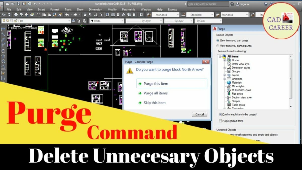
- Select the type of object you want to purge from the Purge dialog box.
- Click the Purge All button to remove all unused objects of the selected type, or select individual items to purge.
- Click OK to complete the purging operation.
3. Toolbar or Tool Palette:
Users can also access the PURGE command from toolbars or tool palettes for quick access and convenience. Simply click on the Purge tool icon in the toolbar or tool palette to activate the PURGE command and follow the prompts to clean up drawing files.
Key PURGE Command Options:
When using the PURGE command in AutoCAD, users can specify various options and parameters to customize the purging operation according to their requirements. Key options include:
- Purge All: Remove all unused objects of the selected type from the drawing, streamlining the purging process for comprehensive cleanup.
- Selective Purge: Select individual items to purge from the drawing, allowing for targeted removal of specific objects or elements.
- Purge Nested Items: Optionally, enable the purge nested items option to remove nested objects or dependencies along with the selected objects, ensuring thorough cleanup and optimization.
Advanced Techniques:
In addition to basic purging methods, AutoCAD offers advanced techniques and tools for enhancing the PURGE command and efficiency:
- Audit and Repair: Use the AUDIT command in conjunction with the PURGE command to detect and repair drawing errors or inconsistencies before purging, ensuring drawing integrity and stability.
- Purge Registered Applications: Enable the purge registered applications option to remove unused objects associated with third-party applications or custom components, optimizing drawing performance and compatibility.
- Purge Unused Layers with LayDel: Utilize the LayDel (Layer Delete) command to purge unused layers along with their associated objects, providing a comprehensive solution for layer cleanup and optimization.
Best Practices:
To achieve optimal results when using the PURGE command in AutoCAD, it’s essential to adhere to the following best practices:
- Regular Maintenance: Incorporate purging into your regular drawing maintenance routine to prevent accumulation of unused objects and ensure drawing file efficiency.
- Review and Preview: Before purging, carefully review the list of unused objects and preview the impact of the purging operation to avoid unintentional deletion of critical elements.
- Backup and Versioning: Always create backup copies of drawing files before purging to safeguard against data loss or unintended changes, and maintain version control for traceability and accountability.
- Document Changes: Document and communicate changes made through the purging process to collaborators or stakeholders to ensure transparency and avoid misunderstandings.
Conclusion:
In conclusion, mastering the PURGE command in AutoCAD empowers designers and drafters to optimize drawing files with precision and efficiency. By understanding the various methods, options, and best practices for using the PURGE command, users can streamline workflows, improve performance, and maintain drawing integrity. With AutoCAD’s versatile tools and features, designers can achieve efficient cleanup and optimization of drawing files, enhancing productivity and collaboration in their projects.