Introduction: Autodesk Inventor is a powerful 3D CAD software widely used by engineers and designers for creating mechanical designs, assemblies, and simulations. While primarily known for its capabilities in traditional mechanical engineering, Autodesk Inventor also provides robust tools for designing hydraulic systems. From pumps and valves to cylinders and actuators, Inventor allows engineers to create, visualize, and analyze complex hydraulic systems with ease. In this comprehensive guide, we’ll delve into the intricacies of designing hydraulic systems in Autodesk Inventor, covering everything from component modeling to system simulation and optimization.
Section 1: Introduction to Hydraulic System Design 1.1 Overview of Hydraulic Systems: Hydraulic systems are used in a wide range of applications, from industrial machinery and construction equipment to automotive braking systems and aircraft flight controls. These systems utilize pressurized fluid to transmit power and control motion, offering advantages such as high force density, precise control, and reliable operation. Designing hydraulic systems requires careful consideration of components, fluid properties, system dynamics, and safety requirements.
1.2 Importance of Hydraulic System Design: Effective hydraulic system design is essential for optimizing performance, efficiency, and reliability while minimizing costs and risks. Engineers must carefully select components, size hydraulic circuits, and design fluid paths to meet performance requirements, ensure system stability, and prevent fluid leakage or component failure. Autodesk Inventor provides powerful tools for modeling, simulating, and analyzing hydraulic systems, enabling engineers to validate designs and optimize performance before physical prototyping.
Section 2: Modeling Hydraulic Components in Autodesk Inventor 2.1 Component Libraries: Autodesk Inventor provides a comprehensive library of standard hydraulic components, including pumps, valves, cylinders, actuators, hoses, fittings, and reservoirs. Engineers can easily access these components from the Content Center library or import custom components from third-party suppliers. Each component in the library is parametrically modeled, allowing engineers to customize dimensions, features, and properties to meet specific design requirements.
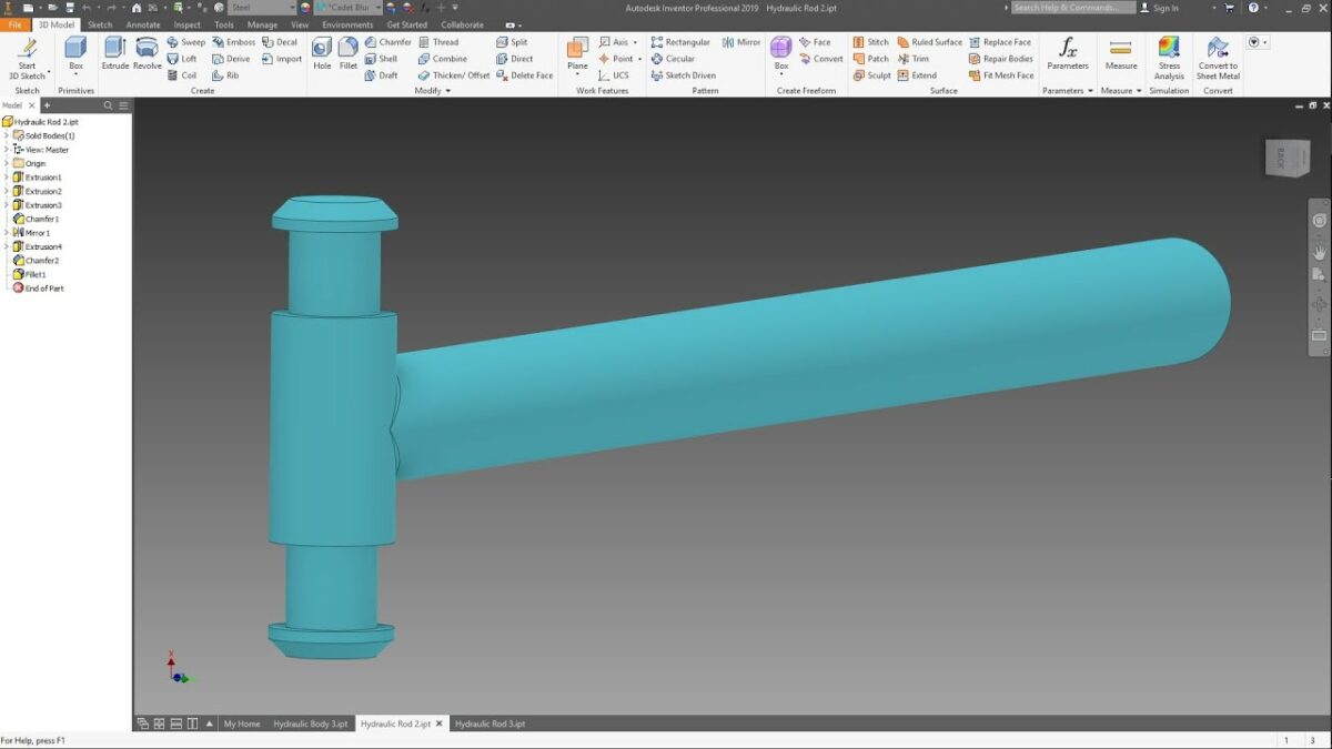
2.2 Component Modeling: Inventor’s parametric modeling environment allows engineers to create custom hydraulic components from scratch or modify existing components to suit specific design needs. Engineers can use sketching, extrusion, revolve, sweep, and loft features to create complex geometries for pumps, valves, cylinders, and other hydraulic components. Constraints and dimensions ensure that components maintain design intent and adapt to changes in the assembly.
Section 3: Assembling Hydraulic Systems in Autodesk Inventor 3.1 Assembly Design: Once hydraulic components are modeled, engineers can assemble them into complete hydraulic systems using Inventor’s assembly design tools. Engineers can use constraints, mates, and relationships to position and connect components within the assembly, ensuring proper alignment, clearance, and functionality. Assembly relationships such as mates, flush, and tangent help simulate real-world interactions between components.
3.2 Piping and Tubing: Inventor’s piping and tubing tools allow engineers to create fluid paths and connect hydraulic components using pipes, tubes, hoses, and fittings. Engineers can define routing preferences, specify pipe sizes, and automatically generate routes between components. Autodesk Inventor’s adaptive routing functionality enables engineers to dynamically adjust routes based on design changes and optimize fluid paths for performance and manufacturability.
Section 4: Simulating and Analyzing Hydraulic Systems 4.1 Hydraulic Simulation: Once the hydraulic system is assembled, engineers can simulate its behavior using Autodesk Inventor’s dynamic simulation tools. Engineers can define operating conditions, such as flow rates, pressures, and actuator movements, and simulate the response of the system to various loading conditions. Inventor’s simulation environment provides visual feedback on system performance, including fluid flow, pressure distribution, and component displacements.
4.2 Performance Analysis: Inventor’s performance analysis tools allow engineers to evaluate the performance of hydraulic systems and identify areas for improvement. Engineers can analyze system efficiency, power consumption, pressure losses, and flow characteristics to optimize system design and component selection. Autodesk Inventor’s parametric analysis capabilities enable engineers to explore design alternatives, evaluate trade-offs, and optimize system performance based on specific design objectives.
Section 5: Optimizing Hydraulic System Design 5.1 Design Optimization: Autodesk Inventor’s optimization tools allow engineers to iteratively refine hydraulic system designs to meet performance, cost, and reliability requirements. Engineers can use parametric optimization techniques to automatically adjust design parameters, such as component sizes, geometries, and operating conditions, to optimize system performance and minimize design constraints. Inventor’s optimization algorithms help engineers identify optimal design solutions that balance competing objectives and constraints.
5.2 Validation and Verification: Before finalizing hydraulic system designs, engineers can validate and verify their performance using Autodesk Inventor’s validation tools. Engineers can conduct virtual tests, simulations, and analyses to ensure that designs meet safety standards, regulatory requirements, and performance specifications. Autodesk Inventor’s integrated validation environment provides real-time feedback on design performance, allowing engineers to iterate and refine designs with confidence.
Section 6: Real-World Applications and Case Studies 6.1 Industrial Hydraulic Systems: Autodesk Inventor is widely used in the design of industrial hydraulic systems for manufacturing, material handling, and process automation. Engineers can use Inventor to model and simulate hydraulic circuits for hydraulic presses, hydraulic lifts, injection molding machines, and hydraulic power units. By optimizing system designs in Inventor, engineers can improve productivity, reduce downtime, and enhance operational efficiency in industrial applications.
6.2 Mobile Hydraulic Systems: In the automotive, construction, and agricultural industries, Autodesk Inventor is used to design hydraulic systems for mobile equipment such as excavators, bulldozers, cranes, and agricultural machinery. Engineers can simulate hydraulic actuation systems, steering systems, and braking systems to optimize performance, reliability, and safety. Inventor’s simulation capabilities help engineers predict and mitigate issues such as cavitation, pressure spikes, and component wear in mobile hydraulic systems.
Conclusion: Autodesk Inventor provides engineers with powerful tools for designing, simulating, and optimizing hydraulic systems for a wide range of applications. By mastering the techniques outlined in this guide and leveraging the capabilities of Inventor’s CAD and simulation platform, engineers can develop innovative hydraulic system designs that meet performance, efficiency, and reliability requirements. With its intuitive interface, parametric modeling tools, and integrated simulation environment, Autodesk Inventor empowers engineers to tackle complex hydraulic system design challenges and bring their ideas to life in the ever-evolving world of engineering and technology.