Introduction:
In the world of engineering and construction, the accuracy and clarity of fabrication drawings play a pivotal role in transforming design concepts into tangible structures. AutoCAD, a powerhouse in Computer-Aided Design (CAD), stands as an indispensable tool for developing fabrication drawings that guide the construction of complex systems. This extensive guide aims to provide comprehensive insights into creating fabrication drawings in AutoCAD, covering essential techniques, industry-specific applications, and best practices for ensuring accuracy in system construction.
Section 1: The Significance of Fabrication Drawings
1.1 Understanding Fabrication Drawings: Fabrication drawings serve as the crucial link between design intent and construction reality. Explore how these drawings communicate precise information about the fabrication, assembly, and construction of complex systems, ensuring that every component is manufactured and installed accurately.
1.2 Importance of Accuracy: Delve into the importance of accuracy in fabrication drawings. From ensuring dimensional precision to specifying materials and detailing assembly instructions, accuracy in fabrication drawings is paramount for successful and efficient system construction.
Section 2: Types of Systems and Fabrication Drawings
2.1 Mechanical Systems: Explore the development of fabrication drawings for mechanical systems. Understand how to represent components such as gears, shafts, and linkages with precision, considering factors like tolerances and material specifications.
2.2 Structural Systems: Delve into the creation of fabrication drawings for structural systems. Learn how to detail components like beams, columns, and connections, providing essential information for construction and assembly.
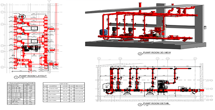
2.3 Piping and Plumbing Systems: Explore techniques for developing fabrication drawings for piping and plumbing systems. Understand how to represent pipes, fittings, and valves accurately, ensuring the seamless integration of these components into the overall system.
Section 3: Setting Up the AutoCAD Environment for Fabrication Drawings
3.1 Template Selection: Begin the fabrication drawing process by selecting the appropriate AutoCAD template. Learn how templates enhance efficiency by providing predefined layers, linetypes, and settings tailored to fabrication documentation.
3.2 Configuring Units and Precision: Ensure precision in fabrication drawings by configuring units and precision settings. Explore the impact of these settings on dimensional accuracy and understand how to align them with project-specific requirements.
Section 4: Creating Base Views and Outlines
4.1 Orthographic Projections: Master the art of creating orthographic projections in AutoCAD for accurate representation of components. Learn to generate base views that serve as the foundation for detailed fabrication drawings, providing a clear understanding of the system’s geometry.
4.2 Exploded Views: Explore the creation of exploded views to illustrate the assembly sequence of components within the system. Understand how strategically disassembling parts visually communicates their relationships and positions, aiding in fabrication and construction.
Section 5: Detailing Components in Fabrication Drawings
5.1 Sectional Views: Delve into the creation of sectional views for detailed components within the system. Learn how sectional views reveal internal features, dimensions, and relationships, enhancing the clarity and understanding of each part.
5.2 Annotations and Dimensions: Explore the addition of annotations and dimensions to individual components. Master the art of conveying critical information such as measurements, materials, and specifications, ensuring clarity and precision in the fabrication drawing.
Section 6: Bill of Materials (BOM) and Parts Lists
6.1 Generating a Bill of Materials: Delve into the extraction of a Bill of Materials (BOM) for fabrication drawings. Learn how to compile information on component types, quantities, and specifications, facilitating material procurement and construction planning.
6.2 Parts Lists and Identifiers: Explore the creation of parts lists and identifiers within fabrication drawings. Understand how to label and identify each component, providing a clear reference for fabrication, assembly, and maintenance.
Section 7: Representing Connectivity and Assembly in Fabrication Drawings
7.1 Welding Symbols: Learn how to represent welding details in fabrication drawings. Explore the use of welding symbols to convey essential information about joint types, weld sizes, and specifications, ensuring accurate fabrication and assembly.
7.2 Fasteners and Joints: Delve into the representation of fasteners and joints within the system. Master techniques for detailing screws, bolts, nuts, and other connection points, providing precise information for fabrication and construction.
Section 8: Customizing Fabrication Drawings for Specific Systems
8.1 HVAC Systems: Explore techniques specific to developing fabrication drawings for Heating, Ventilation, and Air Conditioning (HVAC) systems. Learn how to represent ductwork, components, and connections with precision, considering factors like airflow and system efficiency.
8.2 Electrical Systems: Delve into the customization of fabrication drawings for electrical systems. Understand how to represent wiring, conduits, and electrical components accurately, providing information essential for fabrication and installation.
8.3 Plumbing Systems: Explore techniques for developing fabrication drawings for plumbing systems. Master the representation of pipes, fittings, and fixtures, ensuring accurate fabrication and seamless integration within the overall system.
Section 9: Advanced Techniques for Large and Complex Systems
9.1 Isometric Views: Master the creation of isometric views for large and complex systems. Learn how to represent three-dimensional aspects of the system, providing a comprehensive understanding of spatial relationships and component orientations.
9.2 Representation of Tolerances: Explore techniques for representing tolerances within fabrication drawings. Learn how to communicate acceptable variations in dimensions, ensuring that components fit together accurately during fabrication and assembly.
Section 10: Annotation and Documentation
10.1 Adding System-Level Dimensions: Master the art of adding system-level dimensions. Explore how to provide overall dimensions that encompass the entire system, facilitating a holistic understanding of size and scale during fabrication and construction.
10.2 Detailing and Callouts: Delve into detailing specific areas within the system. Learn to use callouts and detailed views to highlight critical features, ensuring that intricate components are accurately represented and understood during fabrication and assembly.
Section 11: Collaborative Workflows and Data Exchange
11.1 Collaboration with Other Disciplines: Explore collaborative workflows with other disciplines in AutoCAD. Understand how fabrication drawings integrate with mechanical, architectural, electrical, and plumbing disciplines, facilitating coordination and holistic project development.
11.2 Data Exchange with Other Software: Delve into data exchange between AutoCAD and other software platforms. Understand the importance of interoperability in collaborative projects and explore techniques for importing/exporting data to enhance workflow efficiency.
Section 12: Challenges and Troubleshooting
12.1 Common Challenges in Fabrication Drawings: Address common challenges encountered in fabrication drawings. From managing complex system configurations to ensuring accurate representation of connectivity, gain insights into effective problem-solving strategies for creating reliable fabrication documentation.
12.2 Troubleshooting Tips: Explore troubleshooting tips for resolving issues related to fabrication drawings in AutoCAD. From optimizing performance to addressing conflicts with annotations, understand how to maintain precision and stability in your design process.
Section 13: Future Trends and Emerging Technologies
13.1 Building Information Modeling (BIM) Integration: Delve into the potential impact of Building Information Modeling (BIM) integration in fabrication drawings. Explore how BIM enhances collaboration, coordination, and information exchange, streamlining the fabrication and construction process.
13.2 Augmented Reality (AR) for Fabrication Visualization: Explore the integration of augmented reality (AR) with fabrication drawings in AutoCAD. Learn how AR technologies enhance the immersive experience of interacting with and evaluating fabrication designs in real-world contexts.
Conclusion:
As we conclude this exhaustive exploration of developing fabrication drawings for accurate system construction in AutoCAD, it is evident that precision in practice requires a blend of technical proficiency, attention to detail, and an understanding of industry-specific requirements. Whether you are a mechanical engineer detailing components for a complex machine or a structural designer orchestrating the assembly of a building, AutoCAD’s capabilities empower you to produce fabrication drawings that serve as the blueprint for accurate and efficient system construction. Embrace the versatility, efficiency, and customization that AutoCAD offers in fabrication documentation, and witness how this transformative skill elevates your designs from concepts to reality. With continuous practice, exploration, and innovation, you will navigate the intricate landscape of fabrication drawings with confidence, producing documentation that stands as a testament to the power of AutoCAD in the dynamic world of CAD and construction.