Adding a watermark to your videos is a great way to protect your content, brand your videos, and add a professional touch. PowerDirector, a robust video editing software developed by CyberLink, offers various tools and features to help you seamlessly add watermarks to your videos. This comprehensive guide will walk you through the entire process, from creating your watermark to customizing it and applying it to your video.
Understanding Watermarks in PowerDirector
A watermark is a logo, text, or image that is superimposed onto a video to identify the owner or creator. It can serve multiple purposes, including:
- Branding: Promote your brand with a logo or custom text.
- Copyright Protection: Deter unauthorized use of your content.
- Professionalism: Add a polished and professional look to your videos.
PowerDirector supports various types of watermarks, including text-based and image-based, allowing you to choose the style that best suits your needs.
Getting Started with PowerDirector
Before you begin adding a watermark, ensure you have PowerDirector installed on your computer. If you haven’t installed it yet, download and install the latest version from the CyberLink website. Once installed, open PowerDirector and follow these steps:
Step 1: Create a New Project
- Launch PowerDirector: Open the software.
- Start a New Project: Click on “New Project” or select “Create New Project” from the File menu.
Step 2: Import Your Video
- Media Room: Navigate to the “Media Room” tab.
- Import Media: Click on “Import Media Files” and select the video you want to edit.
Creating Your Watermark
Watermarks can be as simple as text or as complex as an image with transparency. Here’s how to create both types of watermarks:
Creating a Text Watermark
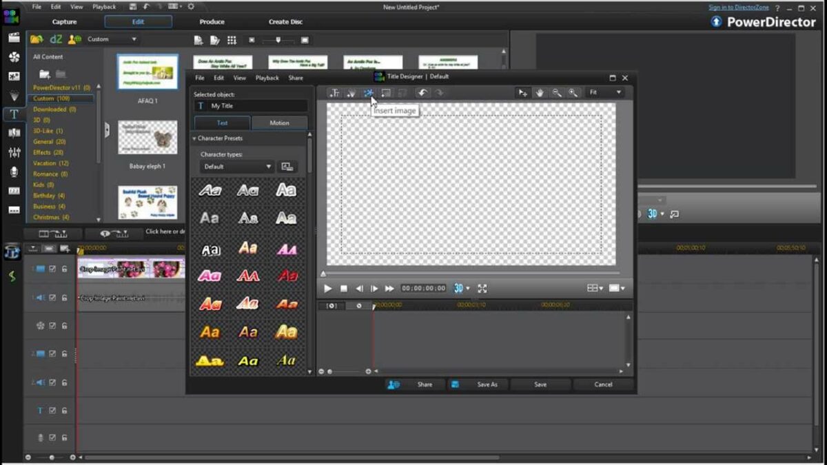
- Navigate to the Title Room: Click on the “Title Room” tab.
- Select a Template: Browse through the templates and choose one that suits your style.
- Customize Your Text: Click on the template to edit the text. Change the font, size, color, and position to match your brand’s aesthetics.
- Save the Title: Once you’re satisfied with the design, save it to your Media Room for easy access.
Creating an Image Watermark
- Design Your Image: Use a graphic design tool like Adobe Photoshop, Canva, or GIMP to create your watermark image. Ensure it has a transparent background (PNG format is ideal).
- Save the Image: Save the image to your computer.
Adding the Watermark to Your Video
With your watermark ready, you can now add it to your video in PowerDirector. Here’s a step-by-step guide:
Step 1: Import the Watermark
- Media Room: Go to the “Media Room” tab.
- Import Watermark: Click on “Import Media Files” and select your watermark image or text title.
Step 2: Add the Watermark to the Timeline
- Drag and Drop: Drag your watermark from the Media Room to the timeline. Place it on a video track above your main video clip.
- Position the Watermark: Click on the watermark clip on the timeline. Use the playback controls to position it where you want on the screen. You can also resize it by dragging the corners of the clip.
Step 3: Customize the Watermark
- Select the Watermark: Click on the watermark clip in the timeline.
- Adjust Properties: Use the “Properties” panel to adjust the transparency, size, and position. You can find these settings under the “Adjust” tab.
Step 4: Fine-Tuning the Watermark
- Transparency: Adjust the opacity to make the watermark blend well with your video. A common opacity value is around 50% to ensure it’s visible but not intrusive.
- Positioning: Place the watermark in a consistent spot, such as the bottom-right or top-left corner, to avoid covering important parts of the video.
Advanced Watermark Features
PowerDirector also offers advanced features to enhance your watermarking process:
Adding Motion to the Watermark
- Select the Watermark: Click on the watermark clip in the timeline.
- Motion Options: Go to the “Motion” tab in the Properties panel. Choose from predefined motion effects or create custom animations to make your watermark dynamic.
Using Multiple Watermarks
- Duplicate Watermark: Right-click on the watermark clip in the timeline and select “Copy.” Then, right-click again and select “Paste” to create a duplicate.
- Customize: Adjust the position, size, and transparency of each watermark to create a layered effect.
Applying Watermarks to Multiple Clips
- Select Multiple Clips: Hold down the Ctrl key and click on the clips in the timeline where you want to apply the watermark.
- Copy and Paste: Right-click on the watermark clip and select “Copy.” Then, right-click on the selected clips and choose “Paste.”
Previewing and Adjusting the Watermark
Before finalizing your video, it’s crucial to preview it to ensure the watermark looks perfect:
- Preview Window: Use the preview window to watch your video and check the watermark’s placement and appearance.
- Adjustments: If the watermark appears too prominent or too subtle, go back to the timeline and adjust the transparency, position, or size.
Exporting Your Watermarked Video
Once you’re satisfied with your watermark and video, you can export it. Here’s how:
Step 1: Produce Your Video
- Go to the Produce Tab: Click on the “Produce” tab at the top of the screen.
- Choose Format: Select your desired output format (e.g., MP4, AVI).
- Select Profile: Choose a preset profile based on your video’s resolution and quality. Click on “Customize Profile” to fine-tune settings like bitrate and frame rate.
Step 2: Export Settings
- Set Output Folder: Choose a destination folder for your exported video.
- File Name: Enter a name for your video file.
- Start Production: Click the “Start” button to begin exporting. PowerDirector will process your video, applying the watermark as specified.
Tips and Best Practices for Watermarking
- Keep It Subtle: A watermark should be visible but not distracting. Avoid using overly large or bright watermarks.
- Consistency: Use a consistent style for your watermarks across all videos to strengthen your brand identity.
- Test Different Positions: Experiment with different positions to find the most effective spot for your watermark.
- Use High-Quality Images: Ensure your watermark image is high resolution to avoid pixelation.
Troubleshooting Common Issues
Issue 1: Watermark Not Displaying
- Solution: Check the transparency and ensure the watermark clip is not muted or hidden. Make sure it’s placed above the video track on the timeline.
Issue 2: Watermark Too Large or Too Small
- Solution: Resize the watermark clip by dragging its corners. Ensure it’s proportional and fits well within the frame.
Issue 3: Watermark Appears Blurry
- Solution: Use a high-resolution image for your watermark. Avoid scaling up a low-resolution image, as it will appear blurry.
Issue 4: Watermark Not Visible in Exported Video
- Solution: Ensure the watermark clip is correctly placed on the timeline and its opacity is set appropriately. Preview your video before exporting to confirm visibility.
Conclusion
Adding a watermark to your video in PowerDirector is a straightforward process that can significantly enhance your content’s professionalism and protect your intellectual property. By following this guide, you can create and customize watermarks, add them to your videos, and export them with ease. Whether you’re a content creator, marketer, or business owner, using watermarks is a crucial step in maintaining brand integrity and ensuring your videos are uniquely yours. Happy editing!