Boiling an egg may seem like a straightforward task, but achieving the perfect boiled egg with a creamy yolk and firm white can sometimes be challenging. Whether you prefer a soft-boiled egg with a runny yolk, a medium-boiled egg with a slightly firm yolk, or a hard-boiled egg with a fully cooked yolk, this comprehensive guide will cover everything you need to know about boiling eggs to perfection. From selecting the right eggs to different cooking methods and timings, let’s dive into the art of boiling eggs.
Step 1: Selecting the Eggs
Choosing the right eggs can impact the outcome of your boiled eggs:
- Freshness: Fresh eggs are generally harder to peel after boiling. For easier peeling, use eggs that are a few days old.
- Size: Use large or extra-large eggs for uniform cooking times and consistent results.
Step 2: Boiling Methods
There are several methods to boil eggs, each yielding slightly different results. Choose the method based on your desired outcome:
Method 1: Soft-Boiled Eggs
Soft-boiled eggs have a runny yolk and firm whites. Here’s how to achieve them:
- Place Eggs in Pot: Place the eggs gently in a single layer at the bottom of a saucepan or pot.
- Add Cold Water: Cover the eggs with cold water, ensuring they are submerged by at least an inch.
- Bring to a Boil: Over medium-high heat, bring the water to a rapid boil.
- Cooking Time:
- Once boiling, reduce the heat slightly to maintain a gentle boil.
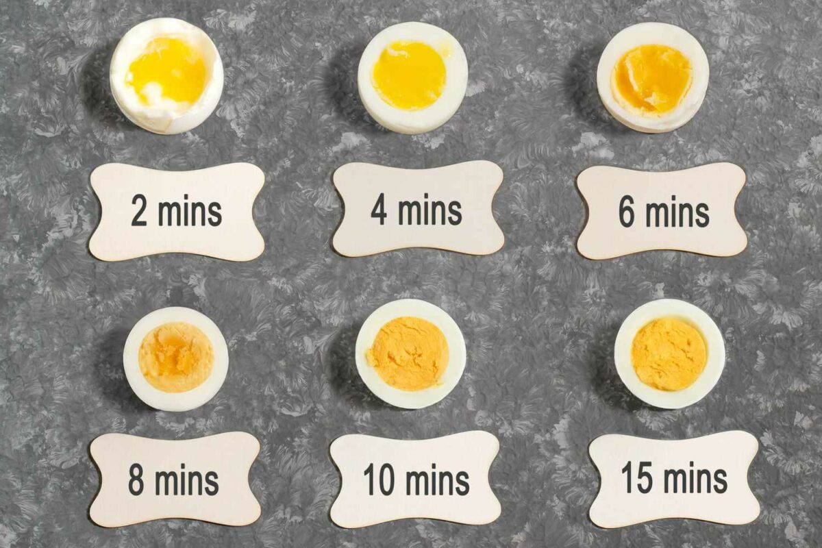
- Cook for 4-6 minutes, depending on the desired firmness of the yolk:
- 4 minutes for a very runny yolk
- 5 minutes for a slightly runny yolk
- 6 minutes for a firmer but still creamy yolk
- Remove and Cool: Use a slotted spoon to transfer the eggs to a bowl of ice water to stop the cooking process immediately.
- Peel and Serve: Gently tap and roll the egg on a hard surface to crack the shell, then peel under cold running water. Serve immediately.
Method 2: Medium-Boiled Eggs
Medium-boiled eggs have a firmer yolk but are still slightly creamy:
- Follow Steps 1-3: Same as for soft-boiled eggs.
- Cooking Time:
- Cook for 7-9 minutes after the water comes to a boil:
- 7 minutes for a softer center
- 8 minutes for a slightly firmer yolk
- 9 minutes for a fully set, but still slightly creamy yolk
- Cook for 7-9 minutes after the water comes to a boil:
- Remove and Cool: Transfer the eggs to a bowl of ice water to cool for a few minutes.
- Peel and Serve: Peel under cold running water and serve immediately or use in recipes.
Method 3: Hard-Boiled Eggs
Hard-boiled eggs have a fully cooked yolk, perfect for salads or as a snack:
- Follow Steps 1-3: Same as for soft-boiled eggs.
- Cooking Time:
- Cook for 10-12 minutes after the water comes to a boil:
- 10 minutes for a creamy center
- 11 minutes for a firm, yet still slightly creamy yolk
- 12 minutes for a fully set yolk
- Cook for 10-12 minutes after the water comes to a boil:
- Remove and Cool: Transfer the eggs to a bowl of ice water to cool completely, around 10 minutes.
- Peel and Serve: Peel under cold running water. Hard-boiled eggs can be stored in the refrigerator for up to one week.
Tips for Success:
- Start with Cold Water: Always start with cold water to prevent eggs from cracking.
- Use a Timer: Timing is crucial for achieving the desired consistency of the yolk.
- Use Fresh Eggs: While slightly older eggs may be easier to peel, fresh eggs can also be successfully boiled with careful handling.
Troubleshooting:
- Green Ring Around Yolk: This happens when eggs are overcooked. Reduce cooking time slightly in future batches.
- Difficult Peeling: If eggs are hard to peel, crack shells all over and peel under cold running water.
Conclusion
Boiling eggs is a simple yet versatile cooking skill that can be adapted to suit various preferences and recipes. Whether you enjoy soft-boiled, medium-boiled, or hard-boiled eggs, mastering the art of boiling eggs ensures you can prepare them perfectly every time. By following the methods and tips outlined in this guide, you’ll be able to enjoy delicious boiled eggs for breakfast, salads, snacks, or as a versatile ingredient in many dishes. Experiment with different cooking times to find your ideal egg consistency, and impress your friends and family with your egg-boiling prowess!