Excel is renowned for its vast array of functions designed to streamline data manipulation and analysis tasks. One such function is CHOOSE, a versatile tool that allows users to select a value from a list of options based on a specified index number. Understanding how to effectively use the CHOOSE function can significantly enhance your ability to organize and manipulate data in Excel. In this comprehensive guide, we’ll explore everything you need to know about using the CHOOSE function, from basic syntax to advanced techniques and real-world applications.
Table of Contents
- Introduction
- Benefits of Using the CHOOSE Function
- Basic Syntax and Usage
- Practical Examples
- Simple Value Selection
- Dynamic Value Selection
- Text and Numeric Options
- Advanced Techniques
- Nesting CHOOSE with Other Functions
- Dynamic Index Number Generation
- Handling Errors and Edge Cases
- Handling Errors
- Common Errors and Troubleshooting
- Ensuring Data Integrity
- Tips and Tricks
- Using CHOOSE for Conditional Formatting
- Optimizing Performance with CHOOSE
- Incorporating CHOOSE into Array Formulas
- Real-World Applications
- Financial Modeling
- Data Analysis
- Reporting
- Best Practices
- Structuring Data for CHOOSE
- Documenting CHOOSE Formulas
- Testing and Validating Results
- Conclusion
1. Introduction
The CHOOSE function in Excel provides a powerful way to select a value from a list of options based on a specified index number. This flexibility makes it a valuable tool for a wide range of tasks, from simple value selection to more complex data manipulation and analysis.
2. Benefits of Using the CHOOSE Function
- Flexibility: Choose from a list of options based on a specified index number.
- Simplicity: Streamline data manipulation tasks with a single CHOOSE formula.
- Efficiency: Perform dynamic value selection without the need for complex nested IF statements.
- Versatility: Use CHOOSE in a variety of scenarios, from basic data validation to advanced data analysis.
3. Basic Syntax and Usage
The basic syntax of the CHOOSE function is as follows:
=CHOOSE(index_num, value1, [value2], ...)
- index_num: The index number that specifies which value to return.
- value1, value2, …: The list of values from which to choose.
4. Practical Examples
Simple Value Selection
To select a value from a list of options based on a specified index number:
=CHOOSE(2, "Option 1", "Option 2", "Option 3")
This formula returns “Option 2” because it corresponds to the second index number.
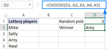
Dynamic Value Selection
To dynamically select a value based on a variable index number:
=CHOOSE(A1, "Low", "Medium", "High")
If cell A1 contains a number between 1 and 3, this formula will return the corresponding value (“Low”, “Medium”, or “High”).
Text and Numeric Options
To choose from a mix of text and numeric options:
=CHOOSE(3, "Red", "Green", 5, 10, 15)
This formula returns the number 5 because it corresponds to the third index number.
5. Advanced Techniques
Nesting CHOOSE with Other Functions
To nest the CHOOSE function within other functions for more complex scenarios:
=VLOOKUP(A1, CHOOSE(B1, Range1, Range2, Range3), 2, FALSE)
This formula uses CHOOSE to dynamically select the lookup range based on the value in cell B1.
Dynamic Index Number Generation
To generate the index number dynamically based on certain criteria:
=CHOOSE(MATCH("Option 2", A1:A3, 0), "Value 1", "Value 2", "Value 3")
This formula uses MATCH to find the position of “Option 2” in the specified range, which determines the index number for CHOOSE.
Handling Errors and Edge Cases
To handle errors or edge cases gracefully:
=IFERROR(CHOOSE(A1, "Option 1", "Option 2", "Option 3"), "Invalid Index")
This formula uses IFERROR to display a custom message (“Invalid Index”) if the index number in cell A1 is not valid.
6. Handling Errors
Common Errors and Troubleshooting
- #VALUE! Error: This error occurs if the index_num argument is not a valid number.
- #NUM! Error: This error occurs if the index number exceeds the number of options available.
- #N/A Error: This error occurs if the index number is not found in the list of options.
Ensuring Data Integrity
Regularly review and validate CHOOSE formulas to ensure that they are returning the expected results and handling errors appropriately.
7. Tips and Tricks
Using CHOOSE for Conditional Formatting
Utilize CHOOSE in conjunction with conditional formatting to dynamically apply formatting based on specific criteria or index numbers.
Optimizing Performance with CHOOSE
When working with large datasets, consider optimizing performance by minimizing the number of options in the CHOOSE function or using alternative lookup methods for faster calculations.
Incorporating CHOOSE into Array Formulas
Take advantage of CHOOSE in array formulas to perform bulk operations or calculations across multiple rows or columns.
8. Real-World Applications
Financial Modeling
Use CHOOSE to categorize financial data into predefined buckets or ranges based on specific criteria or index numbers.
Data Analysis
Apply CHOOSE in data analysis scenarios to segment or classify data into different groups for further analysis or reporting.
Reporting
Incorporate CHOOSE into reporting templates or dashboards to dynamically display different metrics or key performance indicators (KPIs) based on user selections or predefined criteria.
9. Best Practices
Structuring Data for CHOOSE
Organize data in a structured format with clear options and index numbers to facilitate the use of the CHOOSE function.
Documenting CHOOSE Formulas
Document CHOOSE formulas with comments or annotations to explain their purpose, inputs, and expected outputs for future reference.
Testing and Validating Results
Regularly test and validate CHOOSE formulas against known data points or scenarios to ensure accuracy and reliability in real-world applications.
10. Conclusion
The CHOOSE function in Excel is a versatile tool that offers a simple yet powerful way to select a value from a list of options based on a specified index number. By mastering the basic syntax and exploring advanced techniques, users can leverage CHOOSE to streamline data manipulation tasks, automate decision-making processes, and enhance the efficiency of their Excel workbooks. Whether used for basic value selection, dynamic data analysis, or complex reporting scenarios, CHOOSE provides a flexible and efficient solution for a wide range of Excel applications. With its versatility, simplicity, and effectiveness, the CHOOSE function empowers users to unlock the full potential of their data and derive actionable insights that drive informed decision-making and business success.