The GRID command in AutoCAD is a fundamental tool that revolutionizes the way users create, organize, and visualize drawings by providing a customizable grid system. By enabling users to define a grid of evenly spaced reference points or lines within their drawings, the GRID command facilitates precision, alignment, and consistency in the drafting process. In this extensive exploration, we delve into the intricacies of the GRID command in AutoCAD, uncovering its functionality, customization options, and practical applications in various design and drafting scenarios.
Understanding the GRID Command:
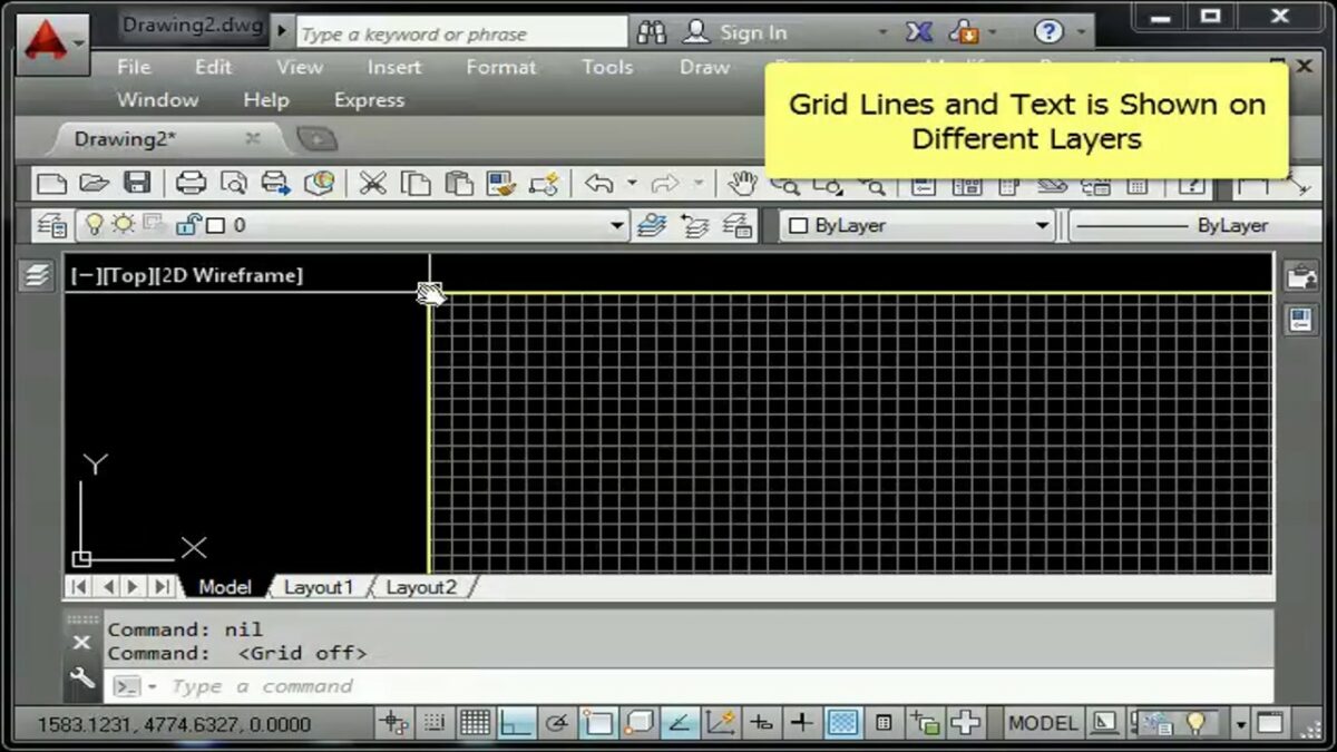
The GRID command in AutoCAD allows users to create and display a grid of evenly spaced reference points or lines within the drawing area. This grid serves as a visual aid for aligning and positioning drawing elements with precision, ensuring accuracy and consistency in the final design.
To activate the GRID command in AutoCAD, users can simply toggle the GRID mode on or off by pressing the F7 key or clicking the Grid Mode button on the status bar. Once enabled, the grid becomes visible in the drawing area, consisting of horizontal and vertical lines spaced at regular intervals according to the specified grid spacing.
Customization Options:
The GRID command offers a range of customization options that allow users to tailor the grid display to their specific needs and preferences. Some of the key customization options include:
- Grid Spacing: Users can specify the spacing of the grid lines, adjusting the distance between grid points or lines to suit the scale and complexity of the drawing. This allows users to create fine-grained grids for detailed drawings or coarse-grained grids for broader layouts.
- Grid Units: Users can specify the units of measurement for the grid spacing, choosing between imperial (inches, feet) or metric (millimeters, meters) units based on their preference. This ensures that the grid spacing is consistent with the units used throughout the drawing.
- Grid Style: Users can customize the appearance of the grid lines, choosing between different line styles, colors, and lineweights to enhance visibility and readability in the drawing area. This allows users to create grids that are easily distinguishable from other drawing elements.
- Grid Extents: Users can specify the extents of the grid display, controlling the area of the drawing in which the grid lines are visible. This allows users to focus on specific regions of the drawing or display the entire grid for reference.
- Snap and Visibility: Users can control the snap behavior and visibility of the grid lines, toggling between snap-to-grid mode and freeform drawing mode as needed. This provides users with flexibility and control over how the grid interacts with other drawing elements.
Practical Applications:
The GRID command has a wide range of practical applications in various design and drafting scenarios. Some common uses of the GRID command include:
- Precision Drawing: The GRID command enables users to create drawings with a high degree of precision and accuracy by aligning drawing elements with the grid lines. This ensures that elements are positioned exactly as intended, reducing errors and inconsistencies in the final design.
- Layout and Composition: The GRID command facilitates layout and composition tasks by providing a framework for organizing drawing elements within the drawing area. Users can use the grid to align objects, create proportional layouts, or establish spatial relationships between elements.
- Dimensioning and Annotation: The GRID command is useful for dimensioning and annotating drawings, allowing users to align dimensions, text, and other annotations with the grid lines for clarity and consistency. This ensures that annotations are positioned accurately and uniformly throughout the drawing.
- Construction and Alignment: The GRID command is invaluable for construction and alignment tasks, providing a reference grid for laying out structural elements, aligning components, or establishing design parameters. Users can use the grid to ensure that elements are aligned and positioned correctly in relation to one another.
- Visual Reference: The GRID command serves as a visual reference for users when creating or modifying drawing elements, providing a framework for visualizing proportions, spacing, and alignment. This helps users maintain design intent and consistency throughout the drawing process.
Conclusion:
The GRID command in AutoCAD is a versatile and indispensable tool that empowers users to create precise, organized, and visually appealing drawings with ease. By providing a customizable grid system, the GRID command enhances precision, alignment, and consistency in the drafting process, enabling users to unlock their full potential and achieve superior results in their designs. Whether used for precision drawing, layout and composition, dimensioning and annotation, construction and alignment, or visual reference tasks, the GRID command remains a cornerstone of modern design workflows, enabling users to master precision and organization in their drawings.